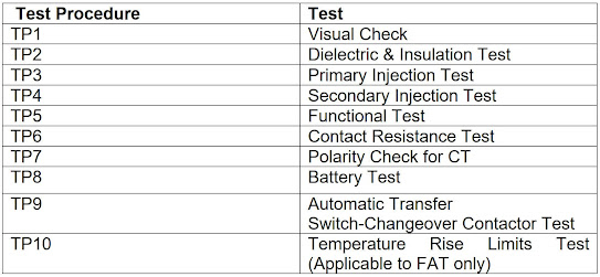
在前一篇,我們介紹了低壓制櫃的FAT和SAT測試中低壓制櫃的Dielectric & Insulation Test 絕緣強度及絕緣電阻測試。見鏈接:
測試目的:
(i) To check the ratio of metering and protection C.T.'s
驗證電流互感器的額定比例值和其綫路是否正確
(ii) To check the spill current of protection C.T.'s
測試電流互感器的剩餘電流
測試儀器:
(i) Primary injection test transformers (初級注入測試變壓器)
(ii) Clamp-on ammeter(s), 0 to 3000A
(iii) Current transformers of appropriate ratings
(iv) Ammeters
測試步驟:
(iv) Ammeters
測試步驟:
(1) Connect the primary injection test set to the circuit breaker under test as shown on the drawing.
(2) Check that the rating of ammeter A1 and ratio of current transformer (TCT) for measurement of the injection current are correct. (首先要確認測試的CT是測量型(MCT)還是保護型(PCT),并在測試表中記錄)
(3) Make sure the circuit breaker under test is at the 'CLOSED' position.
(4) Check all the connections are correct and the control unit is at zero position before switching on the power supply to the control unit.
(5) Increase the supply voltage to the loading unit steadily until the required current output to the circuit breaker under test is applied. This primary current value can be read from the ammeter A1 and verified by a clamp-on ammeter.(至於爲什麽需要鉗形電流表再驗證一次注入電流,我個人的理解是因爲A1表往往是在Primary injection tester上面自帶的電流表(無法進行矯正?)所以需要多一只電流表來保障電流數據正確。)
(6) Normally, the test current shall be equal to the nominal rating of the circuit breaker under test or equal to the primary rating of its protection C.T.'s.
(7) Read the current from ammeter A of the circuit breaker itself (if provided) and record this value in the client-approved test form. The allowable tolerance between 'A1' and 'A' ammeter readings shall not be greater than the sum of the accuracy factors of the metering C.T.'s and the ammeter of both circuits and other error sources. (基於互感器是一個磁電裝置,在感應電路的電流和轉化成爲一個底量值的次級電流時,會出現兩種誤差,分別是額定次級電流與互感器次級輸出電流值的誤差,以及綫路的電流(初級電流)與次級電流的相角差。因爲這樣計算一個保護型電流互感器的縂誤差是十分複雜的,所以以一般合成誤差(Composite Error)表示互感器的縂誤差。)
(8) Read the secondary current and spill current from ammeter A2 by turning the ammeter selector switch 'TS' to its appropriate position. Record these values on the test form. The tolerance of the secondary current should be within +1% for class 5P protection C.T. The spill current should not exceed 2% of the C.T. secondary rating for class 5P protection C.T., i.e. for 5A secondary C.T.'s, the design spill current should be less than 100mA for class 5P protection C.T. The percentage errors here do not include the errors of measuring instruments and other sources.(用以測試並接的保護型電流互感器之間會出現剩餘電流,是因爲在正常情況下,儅各個互感器的輸出電流的“矢量總和”不等於零時,就會出現剩餘電流。而接地故障繼電器(E/F Relay)由於是偵測三個O/C互感器+一個E/F互感器的矢量和電流來運作,E/F Relay則會因爲剩餘電流導致矢量和不爲零超出了額定值而導致錯誤地被啓動。互感器的接綫錯誤、極性倒置,亦或每個互感器比例或精確度不一致,都是產生剩餘電流的原因。)
(9) Carry out the above tests with the current injection tester connected to L1 and L2 phases first and repeat the tests with the tester connect to L2-L3, L3-L1 and L2-N as shown on the client-approved test form.
(10) In case external protection device or protection C.T. have not been incorporated, this primary current injection test may only be carried out to check the ratio of metering C.T.'s. (正常來講,在測試過程中應該保護器件已經安裝到位。)
(11) The designed spill current should not be greater than 100mA.(對於不同的C.T.剩餘電流的要求應該不同。)
測試項目:C.T. Polarity Test 極性測試
測試目的:
To check the polarity of current transformers
要檢查電流互感器的極性
測試儀器:
(i) Analogue multi-function meter
(ii) DC source
測試目的:
To check the polarity of current transformers
要檢查電流互感器的極性
測試儀器:
(i) Analogue multi-function meter
(ii) DC source
測試步驟:
(1) This test can be carried out by connecting an analogue meter to the secondary terminals of the CT and then introducing a D.C. source momentarily to the primary side. The CT is then induced and the pointer of the analogue device moves in the positive direction. This is also known as flick test as the source is D.C., and the thus the CT field is created only once.(這個測試一般是與剩餘電流測試一同進行的,如果在剩餘電流測試中的兩個電流互感器,引起設置方向、接綫不正確引致極性相反時,剩餘電流將會是兩個電流互感器次級電流的綜和。一旦若有電流互感器發現接綫錯誤,可再利用電流表逐個C.T.進行測試)
(2) Record the result on the test form.
測試報告:(Test report is initialled by FED-SUPREMETECH LIMITED)


獲益良多
回覆刪除多謝留言,希望可以同大家交流心得
刪除你好,其實點解會出現spill current?
回覆刪除多謝你的留言。
刪除正常情況下,L1+L2+L3+N 在沒有故障的情況下,相位和應該為零,亦或在誤差允許的範圍內。但當CT的接綫錯誤、極性倒置,亦或每個互感器比例或精確度不一致時,則會產生spill current。例如,四個CT中的某個CT的繞組有問題時,使次級的電流稍大或者稍小,導致L1+L2+L3+N的相位和超出了誤差允許的範圍,這樣會導致E/F有機會錯誤跳脫。因此,spill current需要在誤差允許的範圍內。
終於明白咩叫spill current 喇! 謝謝你的解答!
刪除