顯示包含「電氣設計」標籤的文章。顯示所有文章

2023/01/28

【低壓電容補償櫃】低壓電容補償櫃測試(T&C of LV Capacitor Bank)- 出廠驗收測試(FAT)

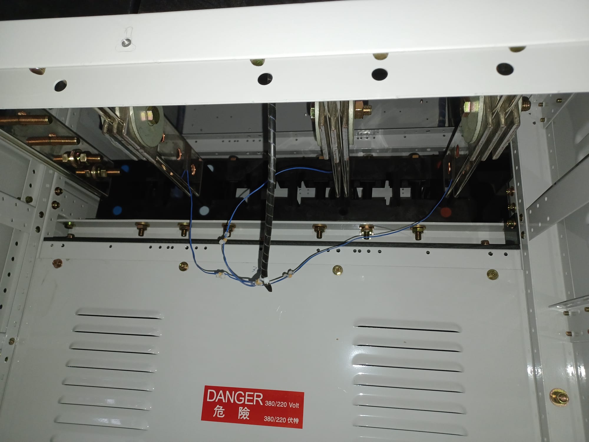
一般來說,低壓電容補償櫃由櫃殼/櫃體、匯流排、斷路器、隔離開關,繼電器、接觸器、電容器、電抗器、一/二次導線、端子排、功率因數自動補償控制裝置、盤面儀表等組成。


電容器補償櫃的作用

電容補償櫃的作用是提高負載功率因數,降低無功功率,提高供電設備的效率;電容櫃是否正常工作可通過功率因數表的讀數判斷(可獨立於櫃面,或者可在功率補償控制器上查看),功率因數一般要求在0.9。


基本元件及其結構


出廠驗收測試(FAT)的主要步驟

1. Visual check (外觀及內部元件檢查)

   Purpose of Test: To check the general construction of the capacitor bank.

   Procedure:

(1) Record the capacitor bank model, serial number and parameters on the attached test form.

(2) Visual inspection for the following items:

    • General appearance inspection.
    • Colour of FBA in accordance with the drawing.
    • The layout of all circuits is in accordance with the drawing.
    • Dimension, clearance and creepage of busbars and risers.
    • Tightness of all screws, bolts and nuts by random check.
    • Complete earthing system.
    • All Main Switches, Fuse Carriers and Controllers operate correctly and freely by hand.
    • Mains cables are phase coloured correctly.
    • Control wirings and ferrules are connected correctly.
    • Capacitor Controllers, Static Switches, Detuned Reactors, Capacitors model, connection and location in accordance with the drawing.
    • Label for circuit identification.
    • Capacitor Bank Cleaning.
    • Check the controller setting.

        (3) Record the result on the test form.


2. Insulation Resistance Test for Main Switchgear & Busbar Chamber / Megger Test (絕緣電阻測試)

   Purpose of Test: To check the insulation of the main switchgear & busbar chamber.

   Procedure:

(1) Check the busbars under test are connected correctly in accordance with the drawing.

(2) Turn off the main switch and all control fuses shall be withdrawed.

(3) Connect the 1000V direct current insulation tester to phase L1 and earth. After each test discharge and earth busbars before disconnection. Check the insulation resistance and record on the approved test form.

(4) Repeat this test on phase to phase, phase to neutral and neutral to earth. The insulation resistance should not be less than 1 MΩ.

(5) Record the result on the test form.


3. Capacitor Bank Charging & Discharging Test and Auto Mode Simulation Test (電容器充放電測試及功率補償控制器自動控制測試)

   Purpose of Test: To check if the capacitor bank charging and discharging normally.

   Procedure:

Manual mode test of the capacitor step switch in/ Out by pressing the “<>” button at the power factor regular

(1) Close the fuse holders feeding the first stage capacitor & provide the minimum current for the P.F. controller.

(2) Press the “<>” button, the first stage capacitor step will switch in instantaneously and the corresponding step indicator in the PFR will come on

(3) Measure the capacitor terminal voltage and current and record the result on the test form

(4) Press the “<>” button, the first stage capacitor step will switch out instantaneously and the corresponding step indicator in the PFR will go out

(5) Open the first stage fuse holder feeding the switched capacitor step, 60 seconds then measure the discharged capacitor terminal voltage and enter the data into the test form

(6) Press “+” or “-“ button to repeat the above procedure for the remaining stage until all stages are tested ( Remark : only one set can be tested at a time.)


Auto mode simulation test of the capacitor step switch In / Out for Power Factor Regulator only

(7) Inject current to Power Factor Regulator to simulate the power factor value, for example, input a current to make the P.F. as 0.89 (any value smaller than 0.90 ) inductive load and the set target P.F. to 0.90 inductive load, the regulator will auto switch in the step of capacitor bank from step 1 to step 6 to make the target P.F. and then change the current flow direction to simulate the over compensation of P.F. and the P.F. will be changed to 0.89 capacitive load from inductive load, and the capacitor bank will be switch out from step 1 to step 6. 

(8) The simulation test of auto mode is completed and record result on the test form


4. Ventilation Fan Function Test (散熱風扇功能測試)

   Purpose of Test: To check the function of the ventilation fan.

   Procedure:

(1) Turn the ventilation fan mode selector into Manual position, the ventilation fan will be turn on permanently.

(2) Turn the Ventilation Fan mode selector into OFF position, the ventilation fan will be turn off permanently.

(3) Turn the ventilation fan mode selector into Auto mode, the ventilation fan will be controlled by the thermostat controller.

(4) Record the result on the test form.


2022/09/24

【低壓制櫃設計】低壓制櫃的測試(T&C of LV Switchboard 2 of 2)- 出廠驗收測試(FAT)和現場驗收測試(SAT)(Part 7)

在前一篇,我們介紹了低壓制櫃的FAT和SAT測試中Function Test 功能測試(TP5),以及ATS的Test (TP9。見鏈接:


Temperature Rise Limits Test 溫升極限試驗是用以測試和確定在額定負載下掣櫃和组件的溫升是否超出標準的極限。一般只在FAT中進行。

在測試中,為確保測試的結果不會受到測試場地的環境因素影響,應在測試階段會使用兩支溫度計在掣櫃的一半高度和相距掣櫃1米外的位置量度室内溫度(ambient air temperature)。

進行溫升極限試驗時,掣櫃的總開關、總匯流排、每一個線路和配電匯流排都應接上其額定容量值的负载。所有電路的额定電流總和,如高於總開關或總匯流排的额定载流量;必須将各個電路组成不同的組合,務求總開關、總匯流排和每個電路都能在滿载下進行測試。當然這是最理想的情況,但常常因為時間的限制,降低測試的次數,而可以免去一些支路匯流排的測試,只對總/主匯流排進行溫升測試。


測試項目:Temperature Rise Limits Test 溫升極限測試
測試目的:
                  To check the temperature rise limit when the circuits are loaded 
測試儀器:  
                  (i) 10 kVA single phase variable transformer
                  (ii) 10 kVA single phase current transformer
                  (iii) 5A secondary current transformer
                  (iv) Thermocouples
                  (v) Temperature loggers
測試步驟:

(1) Arrangement of Test Panel
Check that the arrangement of the L.V Switchboard under test is correct and record all necessary information on the approved test form.

(2) Test Connections
Test connections are fitted to each loaded circuits and short circuited at their remote end from the switchboard with the dimension of test conductors.

Test current for the test is provided via 3 current transformers (1 per phase). These current transformers are connected to three individually variable voltage supplies, one per phase, for the provision of adjustment of the injected current independently. The typical connection method is shown in the figure of this section.

(3) Current Measurement
All outgoing circuits are equipped with one CT for each phase. Each of these CT's is then connected to an ammeter for current measurement. This arrangement facilitates regular monitoring of the intake current and distribution of the current to each test circuit.

(4) Temperature Measurement
Temperatures are measured using thermocouples and temperature loggers.
Thermocouples are adhered to the busbar surface by flame retardant tape at points of particular interest, where high temperatures are likely to be experienced. Details of the positions of thermo-couples are marked on the L.V Switchboard layout drawing.

Ambient temperature is measured from the average of two thermo-couples adhered to both sides of the switchboard at least 1 metre apart from each other and approximately 1.2 metres above the ground.

The locations of the thermocouples are shown on the temperature-rise test drawing. (Test points的數量及位置在測試需要經過業主/工程師審批,一般沿著主bar會儘量在不同節點設置Test points)

(5) Duration of Test
Current is applied until temperature rise approaches the steady state, i.e. rising at not more than 1°C per hour, as stipulated by clause 10.10.2.3.1 of BS EN 61439-1:2011. During this period, slight mains voltage variations and increasing impedance of the test piece necessitate an occasional adjustment to the applied voltage. Temperatures are measured at hourly intervals throughout the test.(Temperature loggers會自動記錄並保存溫度數據)

(6) Test Result
The temperatures measured in each hour are recorded on the client-approved test form. The temperature rise shall not exceed the values as stipulated in Table 6 of BS EN 61439-1:2011.


測試報告:(Test report is initialled by FED-SUPREMETECH LIMITED)


2022/09/12

【電氣設計】電纜大小、電壓降、電能質量計算【進階版 - 施工階段】(Cable Sizing, Voltage Drop and Power Loss Calculation)【Advanced - For Construction】

當工程已經進入到施工階段,我們會根據顧問公司當初設計時提供的電纜大小進行覆核計算。這時,我們常常會遇到有些cable sizing無論如何都解決不了CCC,voltage drop,copper loss等問題。在這時,我們有哪些特別的解決辦法呢?今天,我們就來探討一下。


1. 發電機至末端電纜的copper loss的計算不需要符合BEC的要求。

注意:這裏不僅包括消防(Cat 1)發電機也包括非消防(Cat 2)發電機(常常會忽略非消防發電機,如下圖BEC解釋):


2. 若CCC滿足不了protective device的要求,注意檢查兩點:

    1)檢查電纜數量是否正確,total CCC有無根據電纜數量放大。

    2)檢查電纜的grouping factor是否可以放大。根據CoP,一般情況下grouping factor設置為0.72,但如果電纜橋架只有一條電纜,或者電纜排列較疏,間隔超過一個dia,那麼可以放大,最高至1。

如果檢查之後仍要放大電纜,再去看看保護開關是否預留過大,可否縮小。


3. 當voltage drop和copper loss同時出現Fail狀態時

檢查一下線路的loading是否合理。在施工階段,應該可以基本得到該線纜的實際loading,而不應再使用設計時的預留負荷(預留負荷常常過大)


4. 計算發電機電纜時的負荷不同於正常負荷

在第三點的基礎上,在計算發電機電纜時,線路負載的大小一般不應與正常負載大小相等。因為發電機啟動時的負載一般比正常情況要小。


5. 適當調整預留給末端設備的最後1%

對於Voltage Drop,CoP要求有變壓器supply terminal到末端用電設備的大小不超過4%。在計算時常常計算至末端設備前一端的MCB/MCCB/LMCP為3%,為末端設備預留1%。但如果能證明到末端設備的電壓降小於1%,如供貨商提供的數據或者提供實際計算出來的數值,那麼前部分的3%則可增加至3 ~4 %之間,只要總電壓降不超過4%即可。


6. 覆核電纜長度。

有時為了方便同一間房的電纜常常假設成為統一的一個長度,在施工階段則需要根據實際情況進行覆核。一般會比設計時短一些,這裡需要留意。


以上的六個方法提供了解決電纜計算的六種思路,如果能靈活應用,應該可以解決大部分的電纜計算問題,希望對大家有所幫助。


2022/01/29

【行業介紹】機電業 - 電機工程 職業資歷階梯 能力表 (Units of Competency (Electrical))

香港特別行政區政府教育局於2008年5月5日正式推行資歷架構。香港的資歷架構是一個七級的資歷級別制度,涵蓋學術、職業專才及持續教育及培訓等不同界別,藉此推廣及支持終身學習,並在日益全球化和知識為本的經濟體系中,不斷提升我們工作人口的素質,專業性和競爭力。

職業資歷階梯為行業提供了進修及就業的進階路線圖。進修人士或從業員可透過獲得不同的工作崗位為本資歷,在行業的不同層次得到進一步發展的機會。


職業資歷階梯的主要目的

職業資歷階梯上的崗位為本資歷能證明進修人士已接受足夠的培訓,以及具備從事特定工作的能力,對僱主聘用人才時具有效的參考價值;

協助教育及培訓機構設計更切合行業需要的培訓課程,加強學習與工作之間的連繫;

為年輕人提供行業的就業進階資訊,以吸引他們入行,及協助他們訂定相應的進修計劃; 及

讓有意入職及在職人士掌握不同工作崗位所需要的能力,裝備自己以應付相關工作要求,為個人事業發展作好準備。


政策

設立資歷架構之主要目的是提供一個鼓勵及促進終身學習的平台,以提升香港工作人口的技能及競爭力。

上述目標將透過以下途徑實現:

  • 為學術、職業專才及持續教育界別的資歷釐定明確及客觀的標準;
  • 確保進修人士所獲得的資歷及其相應學習課程的質素;及
  • 確保學習內容能配合行業的需要。


法律框架

立法會於2007 年頒布的《學術及職業資歷評審條例》(第592 章)為教育局局長設立資歷架構及其相關質素保證機制提供法律框架。法例於2008 年5 月5 日全面生效,資歷架構亦同時正式推行。

根據《學術及職業資歷評審條例》,香港學術及職業資歷評審局(簡稱評審局)獲教育局局長委任為評審當局及資歷名冊當局。目前評審局按照其法定的質素保證職能,確保在資歷架構下獲認可資歷的質素及水平。


資歷名冊

資歷名冊(www.hkqr.gov.hk)是一個中央網上資料庫,載列資歷架構認可資歷及其相應進修課程的資料,而所有資歷均通過質素保證程序。

在《學術及職業資歷評審條例》(第592章)下,香港學術及職業資歷評審局被指定為資歷名冊當局。資歷名冊網站於2008年5月5日正式啟用。


2021/12/25

【低壓制櫃設計】低壓制櫃的測試(T&C of LV Switchboard 2 of 2)- 出廠驗收測試(FAT)和現場驗收測試(SAT)(Part 5)

在前一篇,我們介紹了低壓制櫃的FAT和SAT測試中低壓制櫃的Primary Injection Test 初級注入測試。見鏈接:

【低壓制櫃設計】低壓制櫃的測試(T&C of LV Switchboard 2 of 2)- 出廠驗收測試(FAT)和現場驗收測試(SAT)(Part 4)

今天,我們介紹一下FAT和SAT中的Secondary Injection Test 次級注入測試(TP4),次級注入測試的目的是驗證保護繼電器(Protection relay)的準確性。

由於市面上仍比較常見傳統形式的保護繼電器(碟式)繼電器,相比於數字型的保護繼電器,碟式保護繼電器的游絲在運輸途中比較容易受到震蕩而損壞或者出現誤差,因此一般都會在地盤測試時再次進行保護繼電器的測試,因此在SAT和FAT都會進行次級注入測試。


2021/11/07

【低壓制櫃設計】低壓制櫃的測試(T&C of LV Switchboard 2 of 2)- 出廠驗收測試(FAT)和現場驗收測試(SAT)(Part 4)

在前一篇,我們介紹了低壓制櫃的FAT和SAT測試中低壓制櫃的Dielectric & Insulation Test 絕緣強度及絕緣電阻測試。見鏈接:


【低壓制櫃設計】低壓制櫃的測試(T&C of LV Switchboard 2 of 2)- 出廠驗收測試(FAT)和現場驗收測試(SAT)(Part 3)

今天,我們介紹一下FAT和SAT中的Primary Injection Test 初級注入測試(TP3),由於初級注入測試是驗證C.T.的屬性,一般會包括另一項測試Polarity Test for C.T.極性測試(TP7


2021/07/04

【低壓制櫃設計】低壓制櫃的測試(T&C of LV Switchboard 2 of 2)- 出廠驗收測試(FAT)和現場驗收測試(SAT)(Part 2)

在上一篇,我們介紹低壓制櫃的FAT和SAT測試中低壓制櫃的Visual Inspection(目視檢查)。見鏈接:

【低壓制櫃設計】低壓制櫃的測試(T&C of LV Switchboard 2 of 2)- 出廠驗收測試(FAT)和現場驗收測試(SAT)(Part 1)

這一篇,我們介紹一下FAT和SAT中有關的測試儀器儀表以及驗證測量儀器的精度的方式。

關於Verification of Measuring Instrument Accuracy(驗證測量儀器的精度)


測量儀器的精準度影響到整個測試的數據結果,常見的測試儀器以及驗證校準方式/儀器(calibrator)有:

Multimeter 
(Model: Fluke 77-III for reference only)

Multimeter可用廠家提供的校準儀器來校準,例如:
 (Model: Fluke Calibrator 5500A  for reference only)

Megger Tester可用普通的固定阻值的額定電阻(Standard Resistor)來校準,一般會測試多幾隻電阻來對其校準。

2021/06/20

【低壓制櫃設計】低壓制櫃的測試(T&C of LV Switchboard 2 of 2)- 出廠驗收測試(FAT)和現場驗收測試(SAT)(Part 1)

在上一篇,我們介紹了低壓制櫃本身的產品在設計上、製造工藝上需要通過ASTA驗證測試。鏈接:


這一篇,我們重點介紹一下在出廠前,低壓制櫃需要進行的出廠驗收測試(Factory Acceptable Test,FAT)以及運抵工地並完成組裝後,低壓制櫃需要進行的工地現場驗收測試(Site Acceptable Test,SAT)。這一系列的測試中,有些項目是需要在兩地都要進行的,有些項目一般只會在一地進行一次測試即可。而測試的內容,一般是根據顧問公司在招標是訂立的技術標準的要求進行。

2021/05/30

【低壓制櫃設計】低壓制櫃的測試(T&C of LV Switchboard 1 of 2)- ASTA驗證測試

低壓制櫃的測試可以分為三種, 低壓配電櫃本身的產品在設計上、製造工藝上需要通過ASTA驗證測試;出廠前,低壓制櫃需要進行出廠驗收測試(Factory Acceptable Test,FAT);運抵工地並完成組裝後,低壓制櫃需要進行工地現場驗收測試(Site Acceptable Test,SAT)。


2021/05/22

【變電站規劃】變壓器房規劃中的注意事項(Transformer Room Planning 2 of 2)

在較早前的一篇文章中,我們介紹了如何根據負載大小預留變壓器數量從而進一步估計變壓器房的大小。

【變電站規劃】變壓器房規劃中的注意事項(Transformer Room Planning 1 of 2)

今天我們詳細探討一下變壓器房規劃時需要重點注意的地方,我們重點以港燈變壓器房為例,且重點探討一下不超過7m的樓上變壓器房的設置(因為對於非地面層的變壓器房,如果沒有運送變壓器的電梯的話,對於變壓器房的運輸來講是最為複雜的,要求也是最多的),由於地面層的變壓器房相比非地面層的變壓器房規劃起來較為簡單,大家了解了樓上變壓器房的規劃,地面層變壓器房的規劃就會感到得心應手。

2021/05/19

【低壓制櫃設計】低壓制櫃的間隔和形式(Segregation & Form of LV Switchboard)

為了在安裝、調試、以及後期的維修保養過程中更加安全,低壓制櫃一般都會採用間隔設計(segregation/separation)。目的是在對低壓制櫃某一部分進行維修、檢查等工作時,整個制櫃仍可能帶電。間隔是為了防止工作室不慎接觸其他帶電部分,或者從施工裝置掉落物件到相鄰的裝置或其他部分,而導致危險性的事故。而且內部間隔可以在制櫃出現故障時限制不正常現象的蔓延。


2021/05/18

【行業介紹】樓宇建築與機電顧問/工程師(Buildings and MEP Consultant/Engineer)

樓宇建築


建築是建築物與構築物的總稱,是人們為滿足社會生活需要,利用所掌握的物質技術手段,並運用一定的科學規律和美學法則創造的人工環境。

樓宇建築包括,商業和綜合用途建築、教育設施、政府公建、醫療設施、酒店與度假村、資料中心設施、住宅、零售、體育場和競技場館等等。


2021/05/13

【規範標準】香港的電力法規(Electricity Legislation in Hong Kong)

《電力條例》(第406章)(Electricity Ordinance (Cap. 406))是香港電力設計、安裝、檢查(涵蓋發電、輸電和配電設施)的法律基礎。法例旨在保障香港的電力供應以及廣大市民安全合規地使用電力的權利。

《電力條例》同時也制定了一些附屬條例。這些條例包括《電力(線路)規例》(Electricity (Wiring) Regulations)
電力(註冊)規例》(Electricity (Registration) Regulations)電氣產品(安全)規例》(Electrical Products (Safety) Regulation)供電電纜(保護)規例》(Electricity Supply Lines (Protection) Regulation)《電力(豁免)條例》(Electricity (Exemption) Regulations)和其他。機電工程署(EMSD)是香港負責執行《電力條例》及其附屬條例的機構。對於電力顧問工程師,最常用的就是《電力(線路)規例》

不適當地使用電力可能是致命的,因此,通過有效執行現行《電力條例》(第406章)的監管架構,在發電、輸電、配電和用電過程中,相關的風險會大大減少和減輕。


2021/05/08

【變電站規劃】電力公司高壓進線規劃(HV Lead-in Cables Planning)

對於電力公司的高壓進線,在公眾地區,一般是由電力公司進行規劃。一旦進入項目/地盤的私人領域/邊界(Site Boundary),需要業主/顧問公司對進線路徑及鋪設方式進行前期規劃,供電力公司進行審批。

在項目界限內的進線的鋪設方式以及鋪設的線管/線槽/管井,都需要業主提供和安裝,供將來供電公司進行線纜的鋪設。因此,業主需要負責由項目邊界到項目建築內的變壓器房的管井的安裝工程。


2021/04/18

【變電站規劃】變壓器數量及變壓器房規劃(Transformer Room Planning 1 of 2)

在前一篇文章,我們簡單的瞭解到負載估算時可能出現的問題以及可以調整的地方。這一篇我們重點介紹一下如何安排變壓器房時有關變壓器的大小和數量的安排以及需要注意的問題。

樓宇低壓配電系統相對於工業配電系統來說,是比較簡單直接的。香港電力公司最常用的變壓器1500kVA型號,在客戶在用電需求量不足的時候,同時客戶端的供電系統容許的話(或客戶端的供電系統作出升級後),是可以申請升級為2000kVA電容量的變壓器。電力公司用在市區的變壓器主要為1000kVA、1500kVA及2000kVA型號,而郊區用電需求較少時,便會使用200kVA及300kVA型號。近年來,由於項目的用電量逐漸增加,又由於香港的地方寸土寸金,很多項目都是直接上馬2000kVA的變壓器,一是節省空間,二是有利於將來擴容。

2021/03/21

【變電站規劃】負載估算和變壓器大小計算(Loading Estimation & Tx Calculation)

在變電站規劃以及整個樓宇配電系統的規劃的過程中,對於電氣工程師來説最重要的一步也就應該是負載/負荷估算這項工作了。那麽如何有效地進行負載估算,不至於低估或者高估整個項目的負載容量,以及如何確定變壓器大小以及進一步確定變壓器數量,對於初學者來説,是一項挑戰。


2021/03/12

【變電站規劃】中電和港燈的變電站(CLP & HKE Substation Planning)

香港的電力系統


中華電力(中電,CLP)和香港電燈(港燈,HKE)是香港兩間電力公司。作爲壟斷行業,中電主要負責九龍新界地區的輸配電系統,港燈則主要為香港島及南丫島供應電力。由下圖可以看出,中電的輸電網絡佔據了香港大部分的土地。現時,中電為香港約80%人口提供電力,而港燈為香港約20%人口提供電力。


2021/03/03

【發電機設計】發電機功率標準的種類(Generator Power Rating Categories)

發電機組的功率標準 (提及連續功率、主用功率、備用功率、緊急備用功率)


今天我們做一個關於發電機組功率標準的討論,我們嘗試使用日常的語言去替代標準中所使用的語言,看看能否做得更通俗易懂一些。如果我們理解了標準的意義,那麼再去閱讀標準的文本就會更容易接受一些。關於ISO 8528-1的詳細定義,可參考下面的鏈接中第11-15頁: