【低壓制櫃設計】低壓制櫃的測試(T&C of LV Switchboard 2 of 2)- 出廠驗收測試(FAT)和現場驗收測試(SAT)(Part 4)

碟式繼電器

電子(數位式)繼電器

由於碟式保護继電器已经逐步被市場淘汰,我們今天探討的次級注入測試也主要基於對電子式保護繼電器的測試。詳細的碟式保護继電器測試也可以參考EMSD的相關介紹文檔:
測試目的:
To check time/current characteristics of IDMT relays
驗證IDMT繼電器的時間、電流特性
測試儀器:
Secondary Injection Tester / Relay Test Unit
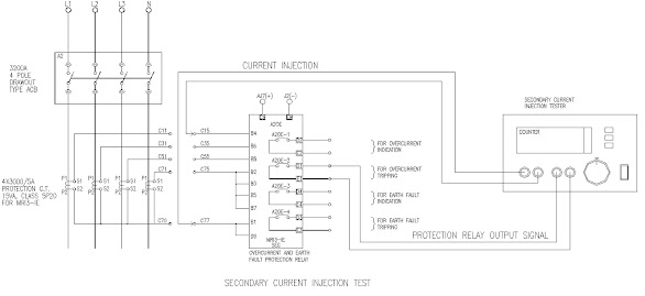
(1) Connect the outgoing cable from the tester to the input circuit of the protection relay under test. Also connect the N/O (normally open) contact circuit of the relay to the time counter of the secondary injection tester.
(2) Connect the power supply to the secondary injection tester.
(3) Check the protection relay type/model is correct.
(4) Record the serial number of the protection relay on the approved test form.
(5) Set the relay at value as shown on the approved test form.
(6) Switch on the tester and set the output current of the tester to the required value. Switch off after correct adjustment.
(7) Switch on the tester again after the relay has been completely reset to start the injection test. The time counter should stop automatically when the relay contact makes. The operating time can be read from that counter.
The acceptable ranges of operating time are shown as below:

(8) A label, stating the final settings (including the current settings, time-multiplier settings and time-current characteristics etc.) of the overcurrent and/or earth-fault protective relay, is affixed near the protective relay. The settings are based on the discriminating curves approved by the client and/or consultant engineer, and such relays will be adjusted to such final settings by FSL test engineers / technicians before the energisation of the LVSB. The final settings are to be provided by the customer based on their fault level and earth fault loop impedance calculations.
(有關discriminating curves的設置,工程師必須在測試前進行審批,承建商需要提交所有回路的保護設備的設置參數以及曲綫以證明上下級保護開關的discrimination達到項目要求。)
沒有留言:
發佈留言
任何人若留有政治言論,個別使用者將會被隔離這個網誌,留言系統或將會被限制,甚至關閉